ASME B16.5 Standard-Pipe Flanges and Flanged Fittings(NPS 1/2 Through NPS 24 Metric/Inch Standard) Materials
ASME B16.5 Pipe Flanges and Flanged Fittings: NPS 1/2 through NPS 24 Metric/Inch Standard covers pressure-temperature ratings, materials, dimensions, tolerances, marking, testing, and methods of designating openings for pipe flanges and flanged fittings.
Haihao Group forged flanges engineering department,design,produce,inspect and supply our forged flanges according to the ASME B16.5 standard.
ASME B16.5 Standard – Pipe Flanges and Flanged Fittings(NPS 1/2 Through NPS 24 Metric/Inch Standard)
- 1. SCOPE
- 2. PRESSURE-TEMPERATURE RATINGS
- 3. COMPONENT SIZE
- 4. MARKING
- 5. MATERIALS
- 6. DIMENSIONS
- 7. TOLERANCES
- 8. PRESSURE TESTING
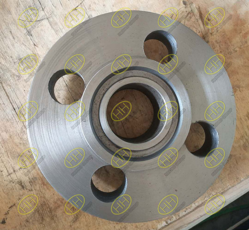
ASME B16.5 socket weld flange
5.MATERIALS
5.1 General
(a)Materials required for flanges and flanged fittings are listed in Table 1.1-1 with the following restrictions:
(1) Plate and flat bar materials may be used only for blind flanges and reducing flanges without hubs.
(2) Flanges and flanged fittings shall be manufactured as one piece in accordance with the applicable material specification.Assembly of multiple pieces into the finished product by welding or other means is not permitted by this Standard.
(b) Each forged flange shall be finished from a part that is brought as nearly as practicable to the finished shape and size by a compressive plastic hot-working operation that consolidates the material to produce an essentially wrought structure,and shall be so processed during the operation as to cause metal flow in the direction most favorable for resisting the stress encountered in service.
(c) Recommended bolting materials are listed in Table 1.1-2(see para. 5.3).
(d) Corresponding materials listed in Section Ⅱ of the ASME Boiler and Pressure Vessel Code may be used provided that the requirements of the ASME specification are identical to or more stringent than the ASTM specification for the Grade,Class,or type of material.
5.1.1 Application. Criteria for the selection of materials are not within the scope of this Standard.The possibility of material deterioration in service should be considered by the user.Carbide phase conversion to graphite and excessive oxidation of ferritic materials,susceptibility to inter-granular corrosion of austenitic materials,or grain boundary attack of nickel base alloys are among those items requiring attention.A discussion of precautionary considerations can be found in ASME B31.3,Nonmandatory Appendix F;Section Ⅱ,Part D,Nonmandatory Appendix A,and Section Ⅲ,Division 1,Nonmandatory Appendix W of the ASME Boiler and Pressure Vessel Code.
5.1.2 Toughness. Some of the materials listed in Table 1.1-1 undergo a decrease in thoughness when used at low temperatures,to the extent that Codes referencing the Standard may require impact tests for application even attemperatures higher than -7℃(+20℉).It is the responsibility of the user to ensure that such testing is performed.
5.1.3 Responsibility. When service conditions dictate the implementation of special material requirements [e.g., using a Group 2 material above 538℃(1000℉)],it is the user’s responsibility to so specify to the manufacturer in order to ensure compliance with metallurgical requirements listed in the notes in Tables 2-1.1 through 2-3.19(Tables 2-1.1C through 2-3.19C).
5.1.4 Cast Surfaces. Cast surfaces of component pressure boundaries shall be in accordance with MSS SP-55,except that all Type Ⅰdefects are unacceptable,and defects in excess of Plates “a” and “b” for Type Ⅱ through Ⅻ are unacceptable.
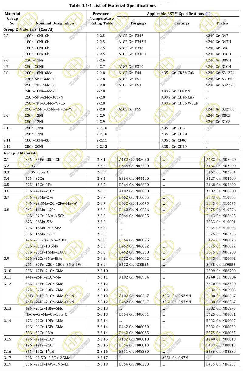
ASME B16.5 Standard Pipe Flanges and Flanged Fittings List of Material Specifications
GENERAL NOTES:
(a) For temperature limitations, see notes in Tables 2.1.1C through 2-3.17C.
(b) Plate materials are listed only for use as blind flanges and reducing flanges without hubs (see para. 5.1). Additional plate materials listed in ASME B16.34 may also be used with corresponding B16.34, Standard Class ratings.
NOTE:
(1) ASME Boiler and Pressure Vessel Code, Section II materials may also be used, provided the requirements of the ASME specification are identical to or more stringent than the corresponding ASTM specification for the Grade, Class, or Type listed.
5.2 Mechanical Properties
Mechanical properties shall be obtained from test specimens that represent the final heat-treated condition of the material required by the material specification.
5.3 Bolting
5.3.1 General. Bolting listed in Table 1.1-2 is recommended for use in flanged joints covered by this Standard.Bolting of other material may be used if permitted by the applicable code or government regulation.Bolting materials are subject to the limitations given in paras. 5.3.2 through 5.3.5.
5.3.2 High-Strength Bolting. Bolting materials having allowable stresses not less than those for ASTM A193 Grade B7 are listed as high strength in Table 1.1-2.These and other materials of comparable strength may be used in any flanged joint.
5.3.3 Intermediate-Strength Bolting. Bolting materials listed as intermediate strength in Table 1B,and other bolting of comparable strength,may be used in any flanged joint provided the user verifies their ability to seat the selected gasket and maintain a sealed joint under expected operating conditions.
5.3.4 Low-Strength Bolting. Bolting materials having no more than 206 MPa (30 ksi) specifed minimum yield strength are listed as low strength in Table 1.1-2.These materials and others of comparable strength are to be used only in Class 150 and 300 flanged joints and only with gaskets described in para.5.4.2.Flanged assemblies using low-strength carbon steel bolts should not be used above 200℃(400℉) or below -29℃(-20℉).
5.3.5 Bolting to Gray Cast Iron Flanges. The following recommendations are made in recognition of the low ductility of gray cast iron:
(a) Alignment of flange faces is essential,along with control of assembly bolt torque,so as not to overstress the cast iron flanges.Care must also be exercised to ensure that piping loads transmitted to cast iron flanges are controlled,taking into account its lack of ductility and recognizing that cast iron flanges should not be used where suddenly applied loads such as rapid pressure fluctuation may occur.
(b) Where Class 150 steel flanges are bolted to Class 125 cast iron flanges,the gaskets should be made of Nonmandatory Appendix B,Table B-1,Group No.Ia materials,the steel flanges should have flat faces,and
(1) low-strength bolting within the limitations of para.5.3.4 should be used with ring gaskets extending to the bolt holes or
(2) bolting of low(para.5.3.4),intermediate (para.5.3.3),or high(para.5.3.2) strength may be used with full face gaskets extending to the outside diameters of the flanges
(c) Where Class 300 steel flanges are bolted to Class 250 cast iron flanges,the gaskets should be made of Nonmandatory Appendix B,Table B-1,Group No.Ia materials
(1) low-strength bolting within the limitations of para. 5.3.4 should be used with gaskets extending to the bolt holes and with the flanges having either raised or flat faces or
(2) bolting of low(para.5.3.4),intermediate(para.5.3.3),or high (para.5.3.2) strength may be used with full face gaskets extending to the outside diameters of the flanges and with both the class 300 steel and Class 250 cast iron flanges having flat faces
5.4 Gaskets
5.4.1 General. Ring joint gasket materials shall conform to ASME B16.20.Materials for other gaskets are described in Nonmandatory Appendix B.The user is responsible for selection of gasket materials that will withstand the expected bolt loading without injurious crushing and that are suitable for the service conditions.Particular attention should be given to gasket selection if a system hydrostatic test approaches or exceeds the test pressure specified in para.2.6.
5.4.2 Gaskets for Low-Strength Bolting. If bolting listed as low strength in Table 1B is used,gaskets shown in Nonmandatory Appendix B,Table B-1,Group No.Ia are recommended.
5.4.3 Gaskets for Class 150 Flanged Joints.It is recommended that only Nonmandatory Appendix B,Table B-1,Group No.I gaskets be used for Class 150 flanged joints.When the ring joint or spiral wound gaskets is selected,it is recommended that line flanges be of the welding neck or lapped joint type.
Related:
ASME B16.5 Welding Neck Flange Dimensions (150lb-2500lb)
ASME B16.5 Slip On Flange Dimensions (150lb-1500lb)
ASME B16.5 Blind Flange Dimensions (150lb-2500lb)
ASME B16.5 Socket Welding Flange Dimensions (150lb-1500lb)
ASME B16.5 Lap Joint Flange Dimensions (150lb-2500lb)
ASME B16.5 Threaded Flange Dimensions (150lb-2500lb)