ASME B16.5 Standard-Pipe Flanges and Flanged Fittings(NPS 1/2 Through NPS 24 Metric/Inch Standard) Pressure-Temperature Ratings
ASME B16.5 Pipe Flanges and Flanged Fittings: NPS 1/2 through NPS 24 Metric/Inch Standard covers pressure-temperature ratings, materials, dimensions, tolerances, marking, testing, and methods of designating openings for pipe flanges and flanged fittings.
Haihao Group forged flanges engineering department,design,produce,inspect and supply our forged flanges according to the ASME B16.5 standard.
ASME B16.5 Standard – Pipe Flanges and Flanged Fittings(NPS 1/2 Through NPS 24 Metric/Inch Standard)
- 1. SCOPE
- 2. PRESSURE-TEMPERATURE RATINGS
- 3. COMPONENT SIZE
- 4. MARKING
- 5. MATERIALS
- 6. DIMENSIONS
- 7. TOLERANCES
- 8. PRESSURE TESTING
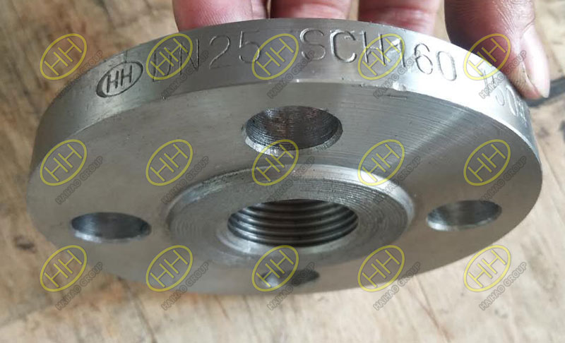
ANSI ASME B16.5 class 150 threaded flange
2.PRESSURE-TEMPERATURE RATINGS
2.1 General
Pressure–temperature ratings are maximum allowable working gage pressures in bar units at the temperatures in degrees Celsius shown in Tables 2-1.1 through 2-3.19 for the applicable material and class designation.Tables 2-1.1C through 2-3.19C list pressure-temperature ratings using psi units for pressure at the t emperature in degrees Fahrenheit. For intermediate temperatures, linear interpolation is permitted. Interpolation between class designations is not permitted.
2.2 Flanged Joints
A flanged joint is composed of separate and independent, although interrelated components: the flanges, gasket, and bolting, which are assembled by another influence, the assembler. Proper controls must be exercised in the selection and application for all these elements to attain a joint that has acceptable leak tightness. Special techniques, such as controlled bolt tightening,are described in ASME PCC-1.
2.3 Rating of Flanged Joints
2.3.1 Basis. Pressure–temperature ratings apply to flanged joints that conform to the limitations on bolting in para. 5.3 and on gaskets in para. 5.4, which are made up in accordance with good practice for alignment and assembly (see para. 2.2). Use of these ratings for flanged joints not conforming to these limitations is the responsibility of the user.
2.3.2 Mixed Flanged Joints. If the two flanges in a flanged joint do not have the same pressure–temperature rating, the rating of the joint at any temperature is the lower of the two flange ratings at that temperature.
2.4 Rating Temperature
The temperature shown for a corresponding pressure rating is the temperature of the pressure-containing shell of the component.In general,this temperature is the same as that of the contained fluid.Use of a pressure rating corresponding to a temperature other than that of the contained fluid is the responsibility of the user,subject to the requirements of applicable codes and regulations.For any temperature below -29℃(-20℉),the rating shall be no greater than the rating shown for -29℃(-20℉)(see also paras. 2.5.3 and 5.1.2).
2.5 Temperature Considerations
2.5.1 General. Use of flanged joints at either high or low temperatures shall take into consideration the risk of joint leakage due to forces and moments developed in the connected piping or equipment.Provisions in paras. 2.5.2 and 2.5.3 are included as advisory with the aim of lessening these risks.
2.5.2 High Temperature. Application at temperatures in the creep range will result in decreasing bolt loads as relaxation of flanges,bolts,and gaskets takes place.Flanged joints subjected to thermal gradients may like-wise be subject to decreasing bolt loads.Decreased bolt loads diminish the capacity of the flanged joint to sustain loads effectively without leakage.At temperatures above 200℃(400℉) for Class 150 and above 400℃(750℉) for other class designations,flanged joints may develop leakage problems unless care is taken to avoid imposing severe external loads,severe thermal gradients,or both.
2.5.3 Low Temperature. Some of the materials listed in Table 1A and 1B,notably some carbon steels,may undergo a decrease in ductility when used at low temperatures to such an extents as to be unable to safely resist shock loading,sudden changes of stress,or high stress concentration.Some codes or regulations may require impact testing for applications even where temperatures are higher than -29℃(-20℉).When such requirements apply,it is the responsibility of the user to ensure these requirements are communicated to the manufacturer prior to the time of purchase.
2.6 System Hydrostatic Testing
Flanged joints and flanged fittings may be subjected to system hydrostatic tests at a pressure of 1.5 times the 38℃(100℉) rating rounded off to the next highe 1 bar(25 psi) increment.Testing at any higher pressure is the responsibility of the user,taking into account the requirements of the applicable code or regulation.
2.7 Welding Neck Flanges
Rating for welding neck flanges covered by this Standard are based upon their hubs at the welding end having thickness at least equal to that calculated for pipe having 276 MPa(40,000 psi) specified minimum yield strength.1 In order to ensure adequate flange hub thickness for flange size NPS 2 and large,the bore of a welding neck flange,dimension B in the various dimensional B in the various dimensional tables,shall not exceed Bmax determined as follows:
Bmax=Ah(1-CoPc/5000)
Where:
Ah=tabulated hub diameter,beginning of chamfer as listed in the dimensional tables
Bmax=maximum permissible diameter for the bore of a welding neck flange
Co=14.5 when Pc is expressed in bar units or 1.0 when Pc is expressed in psi units
Pc=celling pressure value at 38℃(100℉),Tables A-1 and A-2 of Nonmandatory Appendi A
The resultant units for diameter Bmax are the same as those entered for diameter A.
The tabulated rating for welding neck flanges are independent of components to which they may be attached,and the pressure rating of the flanges shall not be exceeded.Attachment welds should be made in accordance with the applicable code or regulation.See pars. 6.7 and Figures 1 through 3 for weld end dimensional requirements.
2.8 Straight Hub Welding Flanges
2.8.1 Hub Dimensions. Straight hub welding flanges have hubs of uniform thickness (see Figure 4).Except as described in paras. 2.8.2 through 2.8.4, the straight hub welding flanges shall have dimensions and tolerances of the welding neck flanges of the same size and class set forth in Tables 8, 11, 14, 16, 18, 20, and 22(Tables 8C, 11C, 14C, 16C, 18C, 20C, and 22C). In Figure 4 the tolerances described in section 7 are applicable.
2.8.2 Length Through Hub. The length through hub shall be 229 mm(9 in.) for NPS 4 and smaller and 305 mm(12 in.) for large than NPS 4.Other lengths may be furnished by agreement between the end user and manufacturer.
2.8.3 Bore. The bore diameter shall be equal to B dimension of the welding neck flange.Other bores may be furnished by agreement between the end user and manufacturer.In no case shall be bore diameter exceed the bore of the same size and class lapped flange.
2.8.4 Hub End. The standard flange shall be provided with square cut end.The end user may specify welding end preparation in accordance with para. 6. 7.
2.9 Multiple Material Grades
Material for flanges and flanged fittings may meet the requirements of more than one specification or the requirements of more than one grade of a specification listed in Table 1A.In either case,the pressure-temperature ratings for any of these specifications or grades may be used provided the material is marked in accordance with para. 4.2.8.
Related:
ASME B16.5 Welding Neck Flange Dimensions (150lb-2500lb)
ASME B16.5 Slip On Flange Dimensions (150lb-1500lb)
ASME B16.5 Blind Flange Dimensions (150lb-2500lb)
ASME B16.5 Socket Welding Flange Dimensions (150lb-1500lb)
ASME B16.5 Lap Joint Flange Dimensions (150lb-2500lb)
ASME B16.5 Threaded Flange Dimensions (150lb-2500lb)