ASME B16.9 Standard-Factory Made Wrought Buttwelding Fittings
The ASME B16.9 standard is an American National Standard,used for factory-made wrought buttwelding fittings in sizes NPS ½ through NPS 48(DN 15 through DN 1200).It covers the information of general scope, pressure ratings, sizes, marking requirement, material, pipe fittings dimensions, butt welding ends preparation, design proof test, test and inspection for products, and the tolerance requirements.
Hebei Haihao Group steel pipe engineering department,design,produce,inspect and supply our butt welding pipe fittings according to the ASME/ANSI B16.9-2012 standard.
Factory-Made Wrought Buttwelding Fittings
- 1 SCOPE
- 2 PRESSURE RATINGS
- 3 SIZE
- 4 MARKING
- 5 MATERIAL
- 6 FITTING DIMENSIONS
- 7 SURFACE CONTOURS
- 8 END PREPARATION
- 9 DESIGN PROOF TEST
- 10 PRODUCTION TESTS
- 11 TOLERANCES
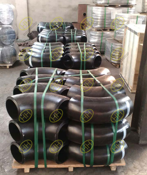
Carbon steel 90 degree elbows
1 SCOPE
1.1 General
This Standard covers overall dimensions,tolerances,ratings,testing,and markings for factory-made wrought buttwelding fittings in sizes NPS ½ through NPS 48 (DN 15 through DN 1200).
1.2 Special Fittings
Fittings may be made to special dimensions,sizes,shapes,and tolerances by agreement between the manufacturer and the purchaser.
1.3 Fabricated Fittings
Fabricated laterals and other fittings employing circumferential or intersection welds are considered pipe fabrication and are not within the scope of this standard.
Fabricated lap joint stub ends are exempt from the above restrictions, provided they meet all the requirements of the applicable ASTM material specification listed in section 5.
1.4 Standard Units
The values stated in either metric or U.S. customary units are to be regarded separately as standard. Within the text, the U.S. customary units are shown in parentheses. The values stated in each system are not exact equivalents; therefore, each system must be used independently of the other. Combining values from the two systems may result in non-conformance with this Standard.
The designation for size is NPS for both metric and customary dimensioned fittings. Fitting pressure rating is associated with the connecting wall thickness of pipe of equivalent size and material.
1.5 References
1.5.1 Referenced Standards.
Standards and specifications adopted by reference in this Standard are shown in Mandatory Appendix II.It is not considered practical to identify the specific edition of each standard and specification in the individual references. Instead, the specific edition reference is identified in Mandatory Appendix II. A product made in conformance with a prior edition of referenced standards and in all other respects conforming to this Standard will be considered to be in conformance.
1.5.2 Codes and Regulations.
A fitting used under the jurisdiction of the ASME Boiler and Pressure Vessel Code,the ASME Code for Pressure Piping, or a governmental regulation is subject to any limitation of that code or regulation. This includes any maximum temperature limitation, or rule governing the use of a material at low temperature.
1.6 Service Conditions
Criteria for selection of fitting types and materials suitable for particular fluid service are not within the scope of this Standard.
1.7 Welding
Installation welding requirements are outside the scope of this Standard.
1.8 Quality Systems
Non-mandatory requirements relating to the fitting manufacturer’s Quality System Program are described in Non-mandatory Appendix A.
1.9 Convention
For the purpose of determining conformance with this Standard, the convention for fixing significant digits where limits (maximum or minimum values) are specified shall be rounded off as defined in ASTM E 29.This requires that an observed or calculated value shall be rounded off to the nearest unit in the last right hand digit used in expressing the limit. Decimal values and tolerances do not imply a particular method of measurement.
1.10 Pressure Rating
Designation Class, followed by a dimensionless number, is the designation for pressure–temperature ratings. Standardized designations for flanges per ASME B16.5 referenced in this Standard are Classes 150, 300, 600, 900, 1500, and 2500.
2 PRESSURE RATINGS
2.1 Basis of Ratings
The allowable pressure ratings for fittings designed in accordance with this Standard may be calculated as for straight seamless pipe of equivalent material (as shown by comparison of composition and mechanical properties in the respective material specifications) in accordance with the rules established in the applicable sections of ASME B31,Code for Pressure Piping. For the calculation, applicable data for the pipe size, wall thickness, and material that is equivalent to that of the fitting shall be used.Pipe size,wall thickness (or schedule number),and material identity on the fittings are in lieu of pressure rating markings.
2.2 Design of Fittings
The design of fittings shall be established by mathematical analyses (e.g., ASME B16.49 for bends) contained in nationally recognized pressure vessel or piping codes,or at the manufacturer’s option by proof testing in accordance with section 9 of this Standard.In order to meet design or manufacturing requirements,it is expected that some portion of formed fittings may have to be thicker than the pipe wall with which the fitting is intended to be used.The mathematical analyses,if used,may take into account such thicker sections.Records of mathematical analysis and/or successful proof test data shall be available at the manufacturer’s facility for inspection by the purchaser.
3 SIZE
NPS,followed by a dimensionless number,is the designation for nominal fitting size.NPS is related to the reference nominal diameter,DN,used in international standards.The relationship is, typically, as follows:
| DN | 15 | 20 | 25 | 32 | 40 | 50 | 65 | 80 | 100 |
| NPS | ½ | ¾ | 1 | 1¼ | 1½ | 2 | 2½ | 3 | 4 |
NOTE: For NPS > 4, the equivalence is DN = 25 x NPS.
4 MARKING
4.1 Standard Marking
Each fitting shall be permanently marked to show the following:
(a) manufacturer’s name or trademark
(b) material identification, either the ASTM or ASME grade designation
(c) schedule number1 or nominal wall thickness in mm
1Schedule number is a dimensionless number that is widely used as a convenient designation for use in ordering pipe and fittings.It is normally associated with a group of standardized pipe wall thickness.Refer to ASME B36.10M and ASME B36.19M for complete details on pipe schedule numbers.
(d) size — the nominal pipe size (NPS) identification number related to the end connections shall be used
(e) compliance — see para. 4.4 for standard and special fitting marking
A manufacturer may supplement these mandatory markings with others, including a DN size designation,but confusion with the required marking shall be avoided.
4.2 Exceptions
Where the size of the fitting does not permit complete marking, the identification marks may be omitted in reverse of the order presented above.
4.3 Depth of Stamping
Where steel stamps are used, care shall be taken so that the marking is not deep enough or sharp enough to cause cracks or to reduce the wall thickness of the fitting below the minimum allowed.
4.4 Compliance
4.4.1 Standard Fittings.
That the fitting was manufactured in conformance with this Standard, including all dimensional requirements, is certified by a prefix “WP” in the material grade designation marking.
4.4.2 Special Fittings.
That the fitting was manufactured in conformance with this standard,except that dimensional requirements are as agreed between the purchaser and the manufacturer,is certified by a supplementary suffix to the material grade designation marking as follows:
(a) “S58” of ASTM A 960 applies for fittings in accordance with ASTM A 234, A 403, and A 420.
(b) “S8” applies for fittings in accordance with ASTM A 815.
(c) “SPLD” applies for fittings in accordance with ASTM B 361, B 363, and B 366.
5 MATERIAL
Wrought fittings covered by this Standard shall be in accordance with ASTM A 234,A 403,A 420,A 815,B 361,B 363, B 366,or the corresponding standard listed in Section II of the ASME Boiler and Pressure Vessel Code.The term wrought denotes fittings made of pipe,tubing,plate,or forgings.Fittings made from block forgings may only be supplied subject to agreement between the manufacturer and purchaser.Such fittings need not meet the requirements of section 7.
6 FITTING DIMENSIONS
6.1 General
This standard provides for a fixed position for the welding ends with reference to either the centerline of the fittings or the overall dimensions. Dimensional requirements for these fittings are to be found in Tables 1 through 11 and Tables I-1 through I-11 of Mandatory Appendix I.
6.2 Special Dimensions
6.2.1 Fatigue Loading.
For applications where fatigue loading is a concern,required minimum dimensions shall be furnished by the purchaser.
6.2.2 Bore Diameter.
Bore diameters away from the ends are not specified.If special flow path requirements are needed,the bore dimensions shall be specified by the purchaser.
6.2.3 Stub Ends.
Service conditions and joint construction often dictate stub end length requirements.
Therefore,the purchaser must specify long or short pattern fitting when ordering.[See General Note (c) in Tables 9 and I-9.]
6.2.4 Segmental Elbows.
Factory-made segments of short radius, long radius, and 3D radius elbows may be made to meet customer angle requirements.With the exception of the B dimension, factory-made segments of elbows shall meet all other requirements of this Standard. The B dimension for segmented elbows can be calculated as follows:
For segments of 90-deg elbows
Bs=A× tan(θ/2)
where
A= dimension A for appropriate 90-deg elbow being segmented from
(a) Table 1/Table I-1 for long radius elbow,mm(in.)
(b) Table 4/Table I-4 for short radius elbow,mm(in.)
(c) Table 6/Table I-6 for 3D elbow, mm(in.)
Bs=center-to-end dimension for segmented elbow
θ=angle of segmented elbow-30 deg,60 deg,75 deg,etc.
When special elbows are intended for field segmenting, the outside or inside diameter tolerance shall be furnished throughout the fitting by agreement between the manufacturer and the purchaser. Any mismatch on the outside or inside diameter needs to be corrected in the field by grinding, back-welding, or bridging of weld to meet the applicable piping code requirements.Although the elbow intended for field-segmenting must meet the requirements of this Standard, once the field-segmented elbow is cut, it is not a B16.9 product.
7 SURFACE CONTOURS
Where adjacent openings in fittings are not in parallel planes, they shall be joined by a circular arc or radius 3 on the external surfaces. The arc or radius may be terminated in tangents. Except as provided for block forgings (see section 5), the projected profile of external surfaces of fittings shall not have sharp intersections (corners) and/or collapsed arcs.
8 END PREPARATION
Unless otherwise specified, the details of the welding end preparation shall be in accordance with Table 12.Transitions from the welding bevel to the outside surface of the fitting and from the root face to the inside surface of the fitting lying within the maximum envelope shown in Fig. 1 are at the manufacturer’s option,except as covered in Note (5) of Fig. 1 or unless otherwise specifically ordered.
9 DESIGN PROOF TEST
9.1 Required Tests
Proof tests shall be made as set forth in this standard when the manufacturer chooses proof testing to qualify the fitting design. Unless otherwise agreed upon between the manufacturer and purchaser, the proof test shall be one based on the computed bursting pressure of the fitting and its connecting piping.
Lap joint stub ends are exempt from proof testing because they are used in a flange assembly,which will have different ratings depending on service application.
9.2 Test Assembly
9.2.1 Representative Components.
Fittings that are representative of production and selected for testing shall be identified as to material, grade, and lot, including heat treatment. They shall be inspected for dimensional compliance to this Standard.
9.2.2 Other Components.
Straight seamless or welded pipe sections whose calculated bursting strength is at least as great as the proof test pressure as calculated in para. 9.3 shall be welded to each end of the fitting to be tested. Any internal misalignment greater than 1.5 mm(0.06 in.) shall be reduced by taper boring at a slope not over 1:3. Length of pipe sections for closures shall be as follows:
(a) Minimum length of pipe shall be one pipe O.D. for NPS 14 (DN 350) and smaller.
(b) Minimum length of pipe shall be one-half pipe O.D. for NPS greater than 14 (DN 350).
9.3 Test Procedure
Test fluid shall be water or other liquid used for hydrostatic testing.Hydrostatic pressure shall be applied to the assembly. The test is successful if the fitting withstands, without rupture, a proof test pressure at least equal to the computed minimum proof test defined below.
P =2St/D
where
D=specified outside diameter of pipe
P=computed minimum proof test pressure for fitting
S=actual tensile strength of the test fitting, determined on a specimen representative of the test fitting, which shall meet the tensile strength requirements of the applicable material of section 5
t=nominal pipe wall thickness of the pipe that the fitting marking identifies
NOTE: Any dimensionally consistent system of units may be used.
9.4 Applicability of Test Results
It is not necessary to conduct an individual test of fittings with all combinations of sizes, wall thicknesses,and materials. A successful proof test on one representative fitting may represent others to the extent described in paras. 9.4.1, 9.4.2, and 9.4.3.
9.4.1 Size Range.
One test fitting may be used to qualify similarly proportioned fittings with a size range from one-half to twice that for the tested fitting. The test of a nonreducing fitting qualifies reducing fittings of the same pattern. The test of a reducing fitting qualifies reductions to smaller sizes.
9.4.2 Thickness Range.
One test fitting may be used to qualify similarly proportioned fittings with t⁄D ranges from one-half to three times that for the tested fitting.
9.4.3 Material Grades.
The pressure retaining capacity of a geometrically identical fitting made of various grades of steel will be directly proportional to the tensile properties of the various grades; see para. 2.1.
Therefore,it is necessary to test only a single material grade in a representative fitting to prove the design of the fitting.
10 PRODUCTION TESTS
Hydrostatic testing of wrought fittings is not required by this Standard. All fittings shall be capable of with standing, without leakage or impairment of serviceability, a hydrostatic test pressure required by the applicable piping code for seamless pipe of material equivalent to the fitting material,and of the size and wall thickness the fitting marking identifies.
11 TOLERANCES
Tolerances for fittings are shown in Tables 13 and I-12,and apply to the nominal dimensions given in Tables 1 through 11 and Tables I-1 through I-11.Where given in the tables,the minimum and maximum dimensions are based on these tolerances.The listings with decimals do not imply precision measurement, such as use of vernier,micrometer,electronic readout equipment,etc.
Dimensions of ASME B16.9 Butt Welding Pipe Fittings:
Table 1: Dimensions of ASME B16.9 Standard 45 degree 90 degree Long Radius Elbows
Table 2: Dimensions of ASME B16.9 Standard 90 degree Long Radius Reducing Elbows
Table 3: Dimensions of ASME B16.9 Standard Long Radius 180 degree Elbows
Table 4: Dimensions of ASME B16.9 Standard 90 degree Short Radius Elbows
Table 5: Dimensions of ASME B16.9 Standard Short Radius 180 degree Elbows
Table 6: Dimensions of ASME B16.9 Standard 45 degree 90 degree 3D Elbows
Table 7: Dimensions of ASME B16.9 Standard Straight Tees and Crosses
Table 8: Dimensions of ASME B16.9 Standard Reducing Outlet Tees and Reducing Outlet Crosses
Table 9: Dimensions of ASME B16.9 Standard Lap Joint Stub Ends
Table 10: Dimensions of ASME B16.9 Standard Caps
Table 11: Dimensions of ASME B16.9 Standard Concentric Reducers and Eccentric Reducers