ASME B16.5 Standard-Pipe Flanges and Flanged Fittings(NPS 1/2 Through NPS 24 Metric/Inch Standard) Dimensions
ASME B16.5 Pipe Flanges and Flanged Fittings: NPS 1/2 through NPS 24 Metric/Inch Standard covers pressure-temperature ratings, materials, dimensions, tolerances, marking, testing, and methods of designating openings for pipe flanges and flanged fittings.
Haihao Group forged flanges engineering department,design,produce,inspect and supply our forged flanges according to the ASME B16.5 standard.
ASME B16.5 Standard – Pipe Flanges and Flanged Fittings(NPS 1/2 Through NPS 24 Metric/Inch Standard)
- 1. SCOPE
- 2. PRESSURE-TEMPERATURE RATINGS
- 3. COMPONENT SIZE
- 4. MARKING
- 5. MATERIALS
- 6. DIMENSIONS
- 7. TOLERANCES
- 8. PRESSURE TESTING
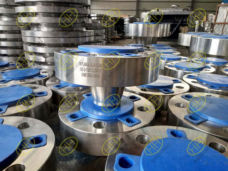
Weld neck flange WN flange A182 Gr F321 RTJ ASME B16.5
6.DIMENSIONS
6.1 Flanged Fittings Wall Thickness
6.1.1 Minimum Wall Thickness. For Inspection purposes,the minimum wall thickness,tm,of flanged fittings at the time of manufacture shall be as shown in Tables 9 and 12(Tables 9C and 12C),except as provided in para.6.1.2.The additional metal thickness needed to withstand installation bolt-up assembly stresses,shapes other than circular,and stress concentrations must be determined by the manufacturer,since these factors vary widely.In particular,45-deg laterals,true Ys,and crosses may require additional reinforcement to compensate for inherent weaknesses in these shapes.
6.1.2 Fitting Local Areas. Local areas having less than minimum wall thickness are acceptable,provide that all of the following conditions are satisfied:
(a) The area of sub minimum thickness can be enclosed by a circle whose diameter is no greater than 0.35√dtm ,where d is the tabulated fitting inside diameter,and tm is the minimum wall thickness as shown in the tables listed in para. 6.1.1.
(b) Measured thickness is not less than 0.75tm.
(c) Enclosure circles are separated from each other by an edge-to-edge distance of more than 1.75√dtm.
6.2 Fitting Center-to-Contact Surface and Center-to-End
6.2.1 Design. A principle of design in this Standard is to maintain a fixed position for the flange edge with reference to the body of the fitting.In case of raised face flanged fittings,the outside edge of the flange includes the raised face (see para. 6.4).
6.2.2 Standard Fittings. Center-to-contact surface,center-to-flange edge,and center-to-end(ring joint) dimensions are shown in Table 9 and 12 (Table 9C and 12C).
6.2.3 Reducing Fittings. Center-to-contact surface or center-to-flange edge dimensions for all openings shall be the same as those of straight size fittings of the largest opening.The contact surface-to-contact surface or flange edge-to-flange edge dimensions for all combinations of reducers and eccentric reducers shall be as listed for the larger opening.
6.2.4 Side Outlet Fittings. Side outlet elbows,tees,and crosses shall have all openings on intersecting centerlines, and the center-to-contact surface dimensions of the side outlets shall be the same as for the largest opening.Long radius elbows with one side outlet shall have the side outlet on the radial centerline of the elbow,and the center-to-contact surface dimension of the side outlet shall be the same as for the regular 90-deg elbow of the largest opening.
6.2.5 Special Degree Elbows. Special degree elbows ranging from 1 deg to 45 deg,inclusive,shall have the same center-to-contact surface dimensions as 45-deg elbows,and those over 45 deg and up to 90 deg,inclusive shall have the same center-to-contact surface dimensions as 90-deg elbows.The angle designation of an elbow is its deflection from straight line flow and is also the angle between the flange faces.
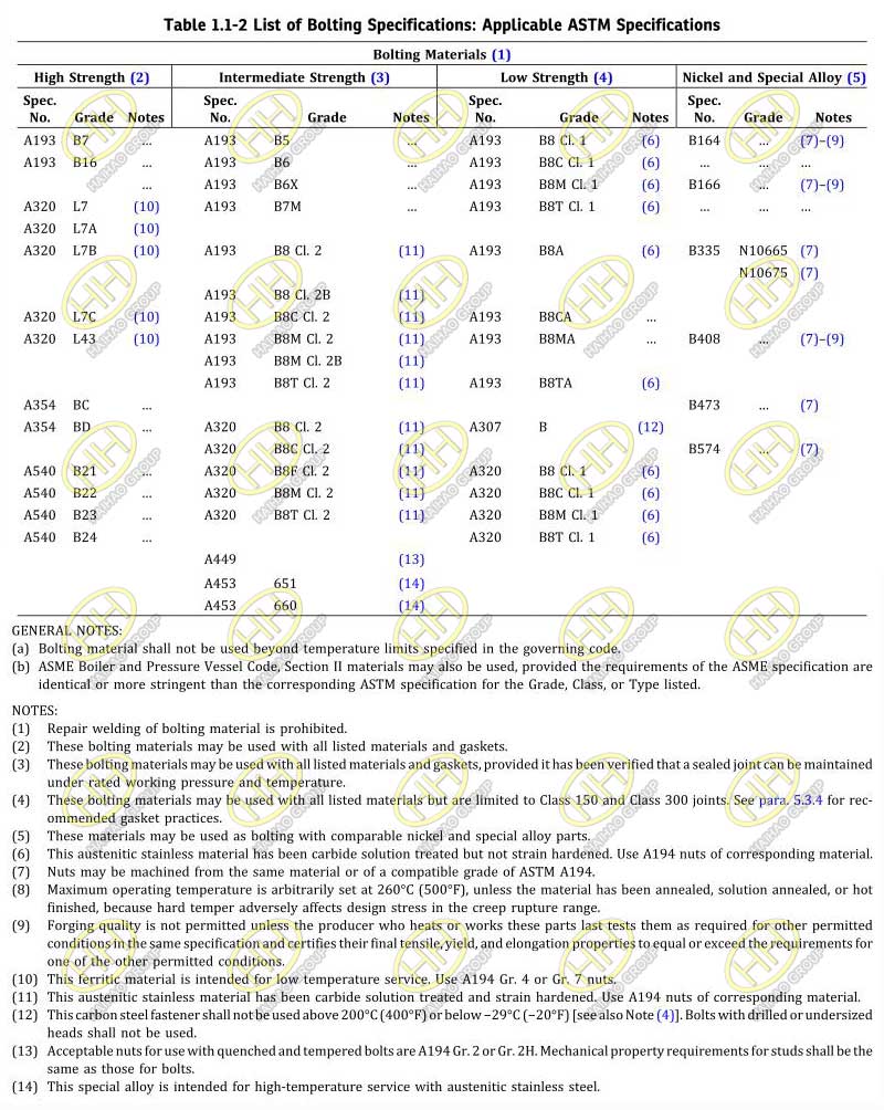
Table 1.1-2 List of Bolting Specifications: Applicable ASTM Specifications
6.3 Flat Face Flanges
6.3.1 General. This Standard permits flat face flanges in all classes.
6.3.2 Conversion. A raised face may be removed from a raised face flange to convert it to a flat face flange,provided that the required dimensions,tf, shown in Figure 6 is maintained.
6.3.3 Facing. The flat face flange facing finish shall be in conformance with para. 6.4.5 for the full width of the seating surface for the gasket.
6.4 Flange Facings
6.4.1 General. Figure 6 shows dimensional relationships for various flange types and pipe lap facings to be used with lap joints.Table 4(Table 4C) lists dimensions for facing other than ring joint.Table 5 (Table 5C) lists dimensions for ring joint facing.Classes 150 and 300 pipe flanges and companion flanges of fittings are regularly furnished with 2 mm(0.06 in.) raised face,which is in addition to the minimum flange thickness,tf .Classes 400,600,900,1500,and 2500 pipe flanges and companion flanges of fittings are regularly furnished with 7 mm(0.25 in.) raised face,which is in addition to the minimum flange thickness tf .
6.4.2 Other Than Lapped Joints. For joints other than lapped joints,the requirements of paras. 6.4.2.1 and 6.4.2.2 shall apply.
6.4.2.1 Raised Face and Tongue Face. In the case of flanges having raised face,tongue,or male face,the minimum flange thickness,tf,shall be provided,and then the raised face,tongue,or male face shall be added thereto.
6.4.2.2 Grooves. For flanges that have a ring joint,groove, or female face, the minimum flange thickness shall first be provided and then sufficient thickness added thereto so that the bottom of the ring joint groove, or the contact face of the groove or female face, is in the same plane as the flange edge of a full thickness flange.
6.4.3 Lapped Joint Flanges. Lapped joint flanges shall be furnished with flat faces as illustrat ed in Tables 8, 11, 14, 16, 18, 20, and 22 (Tables 8C, 11C, 14C,16C, 18C, 20C, and 22C ).Lap joint stub ends shall be in accordance with Figure 6 and paras. 6.4.3.1 through 6.4.3.3.
6.4.3.1 Raised Face. The finished thickness of the lap shall be no less than nominal pipe wall thickness.
6.4.3.2 Large Male and Female. The finished height of the male face shall be the greater of the wall thickness of the pipe used or 7 mm (0.25 in.). The thickness of lap that remains after machining the female face shall be no less than the nominal wall thickness of pipe used.
6.4.3.3 Tongue and Groove. The thickness of the lap remaining after machining the tongue or groove face shall be no less than the nominal wall thickness of the pipe used.
6.4.3.4 Ring Joint. The thickness of the lap remaining after machining the ring groove shall be no less than the nominal wall thickness of pipe used.
6.4.3.5 Lap Joint Facing Outside Diameters. The outside diameters of the lap for ring joints are shown in Table 5 (Table 5C), dimension K. The outside diameters of laps for large female,large tongue and groove, and small tongue and groove are shown in Table 4 (Table 4C). Small male and female facings for lapped joints are not covered by this Standard.
6.4.4 Blind Flanges. Blind flanges need not be faced in the center if, when this center part is raised, its diameter is at least 25 mm (1 in.) smaller than the inside diameter of fittings of the corresponding pressure class, as given in Tables 9 and 12 (Tables 9C and 12C) or 25 mm (1 in.) smaller than the mating pipe inside diameter. When the center part is depressed, its diameter shall not be greater than the inside diameter of the corresponding pressure class fittings, as given in Tables 9 and 12 (Tables 9C and 12C).Machining of the depressed center is not required.
6.4.5 Flange Facing Finish. Flange facing finishes shall be in accordance with paras. 6.4.5.1 through 6.4.5.3,except that other finishes may be furnished by agreement between the user and the manufacturer. The finish of the gasket contact faces shall be judged by visual comparison with Ra standards (see ASME B46.1) and not by instruments having stylus tracers and electronic amplification.
6.4.5.1 Tongue and Groove and Small Male and Female. The gasket cont act surface finish shall not exceed 3.2 μm (125 μm.) roughness.
6.4.5.2 Ring Joint. The side wall surface finish of the gasket groove shall not exceed 1.6 μm (63 μm) roughness.
6.4.5.3 Other Flange Facings. Either a serrated concentric or serrated spiral finish having a resultant surface finish from 3.2 μm to 6.3 μm (125 μm to 250 μm) average roughness shall be furnished. The cutting tool employed should have an approximate 1.5 mm (0.06 in.) or larger radius, and there should be from 1.8 grooves/mm through 2.2 grooves/mm (45 grooves/in. through 55 grooves/in.).
6.4.6 Flange Facing Finish Imperfections. Imperfections in the flange facing finish shall not exceed the dimensions shown in Table 3 (Table 3C). A distance of at least four times the maximum radial projection shall separate adjacent imperfect ions. A radial project ion shall be measured by the difference between an outer radius and inner radius encompassing the imperfection where the radii are struck from the centerline of the bore. Imperfections less than half the depth of the serrations shall not be considered cause for rejection. Protrusions above the serrations are not permitted.
6.5 Flange Bolt Holes
Bolt holes are in multiples of four. Bolt holes shall be equally spaced, and pairs of bolt holes shall straddle fitting centerlines.
6.6 Bolting Bearing Surfaces
Flanges and flanged fittings shall have bearing surfaces for bolting that are parallel to the flange face within 1 deg. Any back facing or spot facing shall not reduce the flange thickness, tf , below the dimensions given in Tables 8, 9, 11, 12, 14, 16, 18, 20, and 22 (Tables 8C, 9C, 11C, 12C, 14C, 16C, 18C, 20C, and 22C ). Spot facing or back facing shall be in accordance with MSS SP-9.
6.7 Welding Neck Flanges Hub and Welding End Profiles
6.7.1 Welding End Profiles.Welding end profiles are illustrated in Figures 1 through 3 and Figures 7 through 10.Other welding end profiles furnished by agreement between the purchaser and manufacture shall not invalidate compliance with this Standard.
6.7.2 Hubs. Acceptable profiles of the hub from the welding end to the back of the flange are shown in Figures 1, 3, 7 and 8.
6.7.3 Bores. Straight-through bores shown in Figures 7 and 8 are required unless the special conditions illustrated in Figures 2, 3, 9, and 10 are furnished by agreement between the purchaser and manufacturer.
6.8 Reducing Flanges
6.8.1 Drilling, Outside Diameter, Thickness, and Facing Dimensions. Flange drilling, outside diameter, thickness, and facing are the same as those of the standard flange of the size from which the reduction is being made.
6.8.2 Hub Dimensions
6.8.2.1 Threaded, Socket Weld, and Slip-On Flanges. The hub dimension shall be at least as large as those of the standard flange of the size to which the reduction is being made. The hub may be larger or omitted as detailed in Table 6 (Table 6C).
6.8.2.2 Welding Neck Flanges. The hub dimensions shall be the same as those of the standard flange of the size to which the reduction is being made.
6.9 Threaded Flanges
6.9.1 Thread Dimensions. Except as provided in Notes (3) of Figure 6 and Note(1) of Table 4 (Table 4C), threaded flanges shall have a taper pipe thread conforming to ASME B1.20.1. The thread shall be concentric with the axis of the flange opening, and variations in alignment (perpendicularity with reference to the flange face) shall not exceed 5 mm/m (0.06 in./ft).
6.9.2 Threads for Class 150 Flanges. Class 150 flanges are made without a counterbore. The threads shall be chamfered approximately to the major diameter of the thread at the back of the flange at an angle of approximately 45 deg with the axis of the thread. The chamfer shall be concentric with the thread and shall be included in the measurement of the thread length.
6.9.3 Threads for Class 300 and Higher Flanges. Class 300 and higher pressure class flanges shall be made with a counterbore at the back of the flange. The threads shall be chamfered to the diameter of the counterbore at an angle of approximately 45 deg with the axis of the threads. The counterbore and chamfer shall be concentric with the thread.
6.9.4 Reducing Flange Thread Length. The minimum length of effective thread in reducing flanges shall be at least equal to dimension T of the corresponding class of threaded flange as shown in Tables 8, 9, 11, 12, 14, 16, 18, 20, and 22 (Tables 8C, 9C, 11C, 12C, 14C,16C, 18C, 20C, and 22C). Threads do not necessarily extend to the face of the flange. See Table 6 (Table 6C) for reducing threaded flanges.
6.9.5 Thread Gaging. Internal threads of flanges shall be checked with gages having a gaging notch.Variations in threading shall be limited to one turn large or one turn small from the gaging notch when using working gages.The reference point for chamfered thread (Class 150) gaging is the starting end of the threaded flange,provided the thread chamfer does not exceed the major diameter of the internal thread.When a chamfer on the internal thread exceeds this limit,the reference point becomes the last thread scratch on this chamfer cone. The reference point foe counterbored thread(Class 300 through 2500) gaging shall be the last thread scratch on the chamfer cone.
6.9.6 Assembly Using Power Equipment. For ASME B1.20.1 external pipe threads, Annex A specifies the distance and number of turns that external pipe threads may be made longer than regular for use with the higher pressure flanges to bring the small end of the thread close to the face of the flange when the parts are assembled by power equipment.
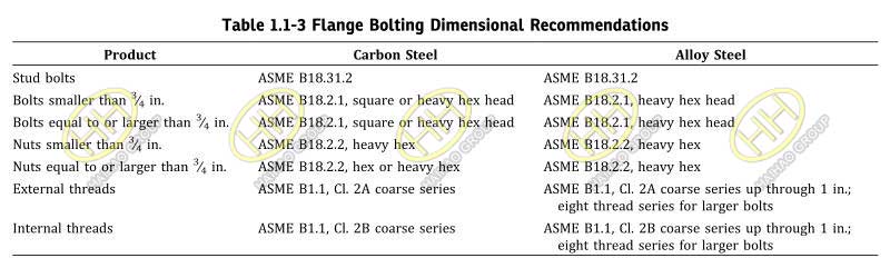
Flange Bolting Dimensional Recommendations
6.10 Flange Bolting Dimensions
6.10.1 Dimensional Standards. Stud bolts, threaded at both ends or threaded full length, or bolts may be used in flange joints. Dimensional recommendations for bolts, stud bolts, and nuts are shown in Table 1.1-3. See para. 5.3 for bolting material recommendations.
6.10.2 Bolt Lengths. Stud bolt lengths, including the height of two heavy hexagon nuts, are shown as dimension L in Tables 7, 10, 13, 15, 17, 19, and 21 (Tables 7C, 10C, 13C, 15C, 17C, 19C, and 21C). The tabulated bolt lengths are reference dimensions.Users may selet other bolting lengths.
6.10.3 Bolting Recommendations. For flange joints, stud bolts with a nut at each end are recommended for all applications and especially for high temperature service.
6.11 Gaskets for Line Flanges
6.11.1 Ring Joint. Ring joint gasket dimensions shall conform to ASME B16.20.
6.11.2 Contact Width. For flanges having large or small tongue-and-groove faces, all gaskets, except solid flat metal gaskets, shall cover the bottom of the groove with minimum clearance. [See para. 7.3(a) for tolerance applicable to groove.] Solid flat metal gaskets shall have contact width not greater than for Nonmandatory Appendix B, Group III gaskets.
6.11.3 Bearing Surface. For flanges with small male-and-female face, care must be taken to ensure that adequate bearing surface is provided for the gaskets. In particular, care is necessary when the joint is made on the end of the pipe as shown in Figure 6.
6.12 Auxiliary Connections
6.12.1 General. Auxiliary connections or openings for flanged fittings are not required unless specified by the purchaser. Welding to attach auxiliary connections to flanged fittings shall be made by a qualified welder using a qualified weld procedure in accordance with Section IX of the ASME Boiler and Pressure Vessel Code.
6.12.2 Pipe Thread Tapping. Holes may be tapped in the wall of a fitting if the metal is thick enough to allow the effective thread length specified in Figure 11.Where thread length is insufficient or the tapped hole needs reinforcement, a boss shall be added.
6.12.3 Sockets. Sockets for socket welding connections may be provided in the wall of a fitting if the metal is thick enough to afford the depth of socket and retaining wall specified in Figure 12.Where the wall thickness is insufficient, or the size of the connection requires opening reinforcement, a boss shall be added (see Figure 13).
6.12.4 Butt Welding. Connections may be attached by butt welding directly to the wall of the fitting (see Figure 14). Where the size of an opening requires reinforcement, a boss shall be added.
6.12.5 Bosses. Where bosses are required, the diameters shall be no less than those shown in Figure 13,and the height shall provide lengths as specified in Figure 11 or Figure 12.
6.12.6 Size. Unless otherwise specified, auxiliary connections shall be of the pipe sizes given below.
| Fitting Size | Connection Size (NPS) |
| 2 ≤ NPS ≤ 4 | 1⁄2 |
| 5 ≤ NPS ≤ 8 | 3⁄4 |
| NPS ≥ 10 | 1 |
6.12.7 Designating Locations. The designation of locations for auxiliary connections for flanged fittings is shown in Figure 15. A letter is used to designate each location.