ASME B16.5 Standard-Pipe Flanges and Flanged Fittings( NPS 1/2 Through NPS 24 Metric/ Inch Standard) Tolerances
ASME B16.5 Pipe Flanges and Flanged Fittings: NPS 1/2 through NPS 24 Metric/Inch Standard covers pressure-temperature ratings, materials, dimensions, tolerances, marking, testing, and methods of designating openings for pipe flanges and flanged fittings.
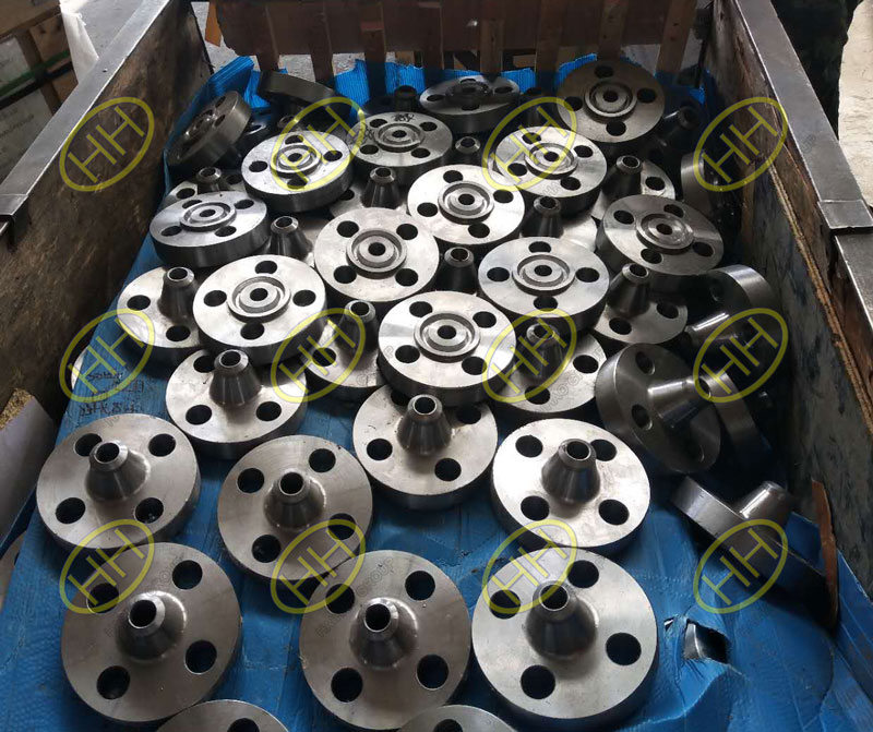
Haihao Group forged flanges engineering department,design,produce,inspect and supply our forged flanges according to the ASME B16.5 standard.
ASME B16.5 Standard – Pipe Flanges and Flanged Fittings(NPS 1/2 Through NPS 24 Metric/Inch Standard)
- 1. SCOPE
- 2. PRESSURE-TEMPERATURE RATINGS
- 3. COMPONENT SIZE
- 4. MARKING
- 5. MATERIALS
- 6. DIMENSIONS
- 7. TOLERANCES
- 8. PRESSURE TESTING
ANSI ASME B16.5 class 1500 A350 LF2 weld neck flanges
7 TOLERANCES
7.1 General
For the purpose of determining conformance with this Standard, the convention for fixing significant digits where limits, maximum or minimum values, are specified shall be rounded as defined in ASTM Practice E 29. This requires that an observed or calculated value shall be rounded to the nearest unit in the last right-hand digit used for expressing the limit. The listing of decimal tolerances does not imply a part icular method of measurement.
7.2 Center-to-Contact Surfaces and Center-to-End
Required tolerances for various flanges and flanged fitting elements are as follows:
(a) Center-to-Contact Surfaces Other Than Ring Joint
| Size | Tolerance, mm (in.) |
| NPS ≤ 10 | ±1.0 (±0.04) |
| NPS ≥ 12 | ±1.5 (±0.06) |
(b) Center-to-End (Ring Joint)
| Size | Tolerance, mm (in.) |
| NPS ≤ 10 | ±1.0 (±0.04) |
| NPS ≥ 12 | ±1.5 (±0.06) |
(c) Contact Surface-to-Contact Surface Other Than Ring Joint
| Size | Tolerance, mm (in.) |
| NPS ≤ 10 | ±2.0 (±0.08) |
| NPS ≥ 12 | ±3.0 (±0.12) |
(d) End-to-End (Ring Joint)
| Size | Tolerance, mm (in.) |
| NPS ≤ 10 | ±2.0 (±0.08) |
| NPS ≥ 12 | ±3.0 (±0.12) |
7.3 Facings
Tolerances that apply to both flange and flanged fitting facings are as follows:
(a) Inside and outside diameter of large and small tongue and groove and female,±0.5 mm (±0.02 in.).
(b) Outside diameter, 1.5 mm (0.06 in.) raised face, ±1.0 mm (±0.03 in.).
(c) Outside diameter, 6.4 mm (0.25 in.) raised face, ±0.5 mm (±0.02 in.).
(d) Ring joint groove tolerances are shown in Table 5 (Table 5C).
Tolerances that apply to flanges are as follows:
(e) Perpendicularity of the face with the bore
| Size | Tolerance, deg |
| NPS ≤5 | 1 |
| NPS ≥ 6 | 0.5 |
7.4 Flange Thickness
Required tolerances for flange thickness are as follows:
| Size | Tolerance, mm (in.) |
| NPS ≤ 18 | +3.0, -0.0(+0.12, -0.00) |
| NPS ≥20 | +5.0, -0.0(+0.12, -0.00) |
The plus tolerance is applicable to bolting bearing surfaces whether as-forged, as-cast, spot-faced, or backfaced (see para. 6.6).
7.5 Welding End Flange Ends and Hubs
7.5.1 Outside Diameter. Required tolerances for the nominal outside diameter dimension A of Figures 7 and 8 of welding ends of welding neck flanges are as follows:
| Size | Tolerance, mm (in.) |
| NPS ≤ 5 | +2.0, -1.0(+0.08, -0.04) |
| NPS ≥6 | +4.0, -1.0(+0.16, -0.04) |
7.5.2 Inside Diameter. Required tolerances for the nominal inside diameter of welding ends of welding neck flanges and smaller bore of socket welding flanges (dimension B in the referenced figures) are as follows:
(a) For Figures 4, 7 and 8, the tolerances are
| Size | Tolerance, mm (in.) |
| NPS ≤ 10 | ±1.0(±0.04) |
| 12≤NPS ≤18 | ±1.5(±0.06) |
| NPS≥20 | +3.0, -1.5 (+0.12, -0.06) |
(b) For Figure 9, the tolerances are
| Size | Tolerance, mm (in.) |
| NPS ≤ 10 | +0.0, -1.0(+0.0, -0.04) |
| NPS ≥12 | +0.0, -1.5(+0.0, -0.06) |
7.5.3 Backing Ring Contact Surface. Required tolerances for the bore of the backing ring contact surface of welding neck flanges, dimension C of Figures 9 and 10 are as follows:
| Size | Tolerance, mm (in.) |
| 2≤NPS ≤ 24 | +0.25, -0.0(+0.01, -0.0) |
7.5.4 Hub Thickness. Despite the tolerances specified for dimensions A and B, the thickness of the hub at the welding end shall not be less than 87 ½% of the nominal thickness of the pipe, having an under-tolerance of 12.5% for the pipe wall thickness to which the flange is to be attached or the minimum wall thickness as specified by the purchaser.
7.6 Length Through Hub on Welding Neck Flanges
The required tolerances for the length through hubs on welding neck flanges are as follows:
| Size | Tolerance, mm (in.) |
| NPS ≤ 4 | ±1.5(±0.06) |
| 5≤NPS ≤10 | ±1.5, -3.0(±0.06, -0.12) |
| NPS≥12 | +3.0, -5.0 (+0.12, -0.20) |
7.7 Flange Bore Diameter
7.7.1 Lapped and Slip-On Flange Bores. The required tolerances for lapped and slip-on flange bore diameters are as follows:
| Size | Tolerance, mm (in.) |
| NPS ≤ 10 | +1.0, -0.0(+0.04, -0.0) |
| NPS ≥12 | +1.5, -0.0(+0.06, -0.0) |
7.7.2 Counterbores, Threaded Flanges. The required tolerances for threaded flange counterbores are as follows:
| Size | Tolerance, mm (in.) |
| NPS ≤ 10 | +1.0, -0.0(+0.04, -0.0) |
| NPS ≥12 | +1.5, -0.0(+0.06, -0.0) |
7.7.3 Counterbores, Socket Welding Flanges. The required tolerances for socket end counterbores is as follows:
| Size | Tolerance, mm (in.) |
| ½≤NPS ≤ 3 | ±0.25(±0.010) |
7.8 Drilling and Facing
7.8.1 Bolt Circle Diameter. The required tolerance for all bolt circle diameters is as follows:
±1.5 mm (±0.06 in.)
7.8.2 Bolt Hole to Bolt Hole. The required tolerance for the cent er-to-cent er of adjacent bolt holes is as follows:
±0.8 mm (±0.03 in.)
7.8.3 Bolt Circle Concentricity. The required tolerances for concentricity between the flange bolt circle diameter and machined facing diameters are as follows:
| Size | Tolerance, mm (in.) |
| NPS ≤2 ½ | 0.8(0.03) |
| NPS ≥3 | 1.5 (0.06) |